


Introduction
Understanding pull-up resistors is essential for anyone involved in electronics, from hobbyists to professional engineers. These simple yet powerful passive components ensure the reliability and stability of digital circuits. Mastering pull-up resistors can greatly enhance beginners’ electronic project outcomes and make their devices more robust and dependable. This guide provides a detailed overview of pull-up resistors, explaining their purpose, significance, types, how to design, and how they work and are used in various electronic applications.
Understanding Floating Inputs in a Circuit
Before delving into the introduction of pull-up resistors, it is essential to understand what floating inputs in a circuit are. In electronic circuits, “floating inputs” refer to input pins of a device (like a microcontroller, logic gate, or integrated circuit) that are not connected to a definite voltage level. This means they are neither driven to a logic high state nor pulled down to a logic low state. As a result, the state of these inputs is undetermined and can unpredictably fluctuate due to electrical noise or interference.
Floating inputs are typically undesirable because they can lead to erratic behaviour or increased power consumption in digital circuits. To prevent this, inputs are usually tied to a known voltage through using pull-up or pull-down resistors. This ensures that the inputs have a stable and predictable state when another circuit element is not actively driving them.
What is a Pull-Up Resistor? Know Its Fundamental Purpose
A pull-up resistor is a fixed-value passive component used in digital circuits to ensure your circuits avoid unwanted signals generated during their floating states. These high-performance resistors ensure the integrated wire is pulled to a high logical level when there is no input signal. The primary purpose of a pull-up resistor is to avoid floating inputs that can lead to unpredictable behaviour in digital circuits. Floating inputs may pick up noise, leading to erratic output states. By using a pull-up resistor, you ensure the input pin is always in a defined state, either high or low, depending on the circuit’s design.
The Importance of Using Pull Up Resistors in Digital Circuits
In digital circuits, it’s crucial to avoid floating inputs, which can lead to unpredictable behaviour. These resistors prevent this by ensuring that the input pins have a defined voltage level, thereby stabilising the circuit’s operation. Additionally, using a pull-up resistor in digital circuits enhances noise immunity and prevents erroneous readings, thus ensuring the operational reliability and stability of circuits.
The Operating Principle of Pull-Up Resistors
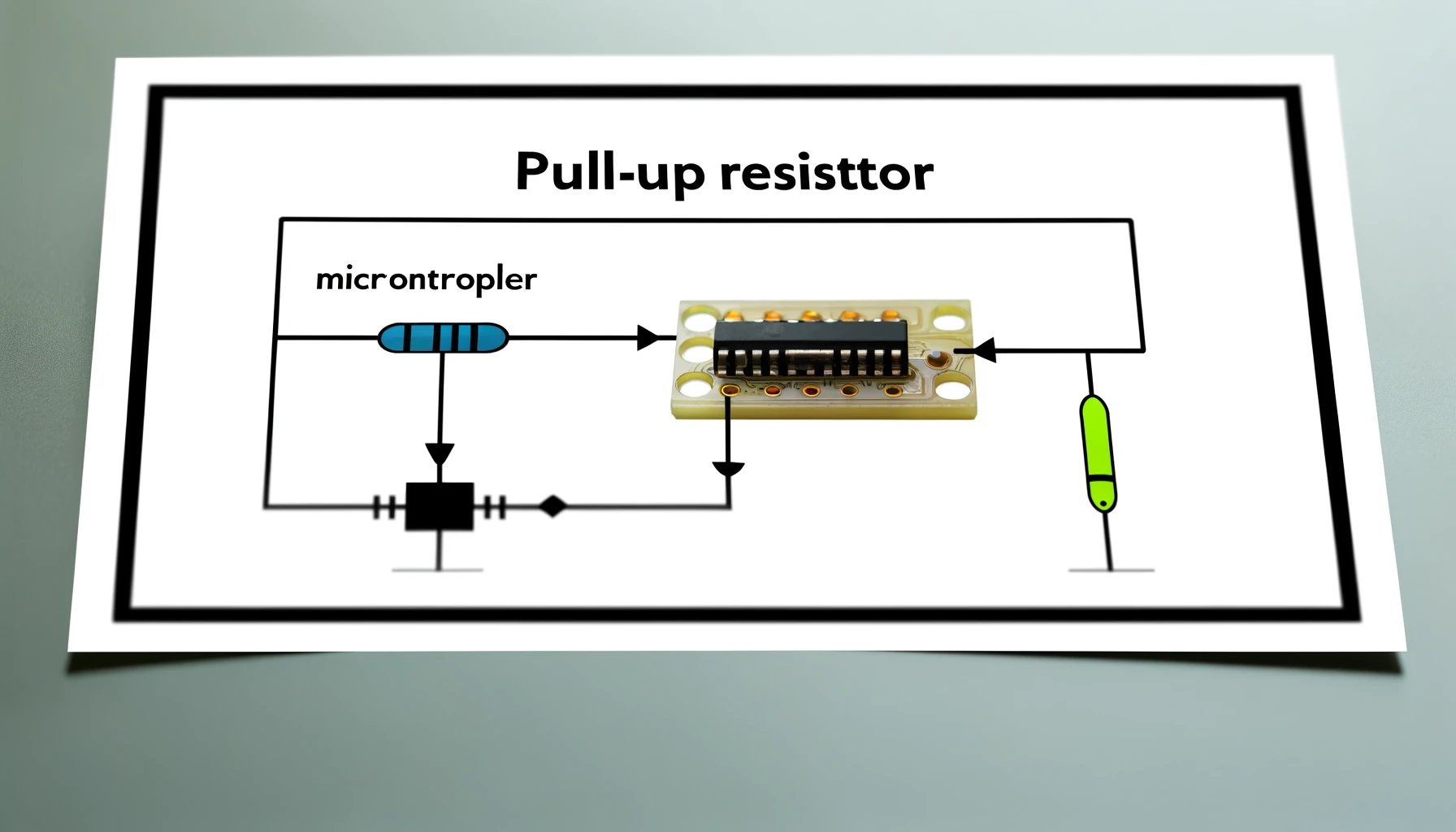
A pull-up resistor connects between the positive supply voltage and the particular pin on the device, which might otherwise float. When no other device is actively driving the pin low, the resistor pulls the pin to the high state (i.e., connected to the supply voltage). When another device, like a switch, connects the pin to the ground, it overrides the pull-up resistor, bringing the pin to a low state.
Most Common Types of Pull-Up Resistors
There are two common types of pull-up resistors: internal and external.
- Internal Pull-Up Resistors – Some microcontrollers and integrated circuits (ICs) have built-in pull-up resistors that can be enabled or disabled through software configuration. These internal pull-up resistors simplify circuit design by eliminating the need for external components.
- External Pull-Up Resistors – External pull-up resistors are discrete components connected externally to the circuit. They offer more flexibility in terms of value selection and are used in a broader range of applications.
Pull-Up vs. Pull-Down Resistors: Exploring the Key Differences and When to Use Each
While pull-up resistors pull the input to a high logic level, pull-down resistors work opposite, pulling the input to a low logic level. The selection choice between a pull-up or pull-down resistor depends on the circuit’s specific requirements. For instance, these resistors are often used in open-drain or open-collector configurations, whereas pull-down resistors are used when you need a default low state.
Simple Steps to Designing a Pull-Up Resistor Circuit
When designing a pull-up resistor circuit, it’s essential to calculate the appropriate resistor value to ensure optimal performance. This involves considering the input’s high threshold voltage and the maximum input current of the driving circuit. Following the given basic steps can help you design a pull-up circuit:
- Identify Voltage Levels: Determine your circuit’s operating voltage and the logic levels required by your microcontroller or digital system.
- Choose Resistor Value: Select a resistor that effectively pulls the line to a high state without causing excessive current draw. A commonly used value for many applications is 10kΩ.
- Circuit Integration: Integrate the resistor with the other components. For instance, connect one end of the resistor to the power supply and the other to the line leading to the digital input.
Real-World Applications of Pull-Up Resistors
These resistors are inexpensive yet critical components in the functioning of various electronic circuits and applications, including:
- GPIO Pin State Control
- I2C Bus Communication
- Button Interfaces
- Reset Circuits
- Logic Level Shifting
- Debouncing Switches
- Wire-OR Connections.
Takeaway
These resistors are essential components in digital circuits, ensuring signal integrity and preventing undefined states. By understanding various aspects of these resistors outlined in the article, beginners can design reliable and robust electronic circuits for numerous applications. Whether you’re building a simple push-button interface or implementing complex communication protocols, pull-up resistors are significant in ensuring the proper operation of your circuits.
Related posts:
 Cinch Connectivity Solutions 101| Cinch Connectors
 How STM32Trust Ensures Commercial Security
 7 Different Types of Fixed Resistors and their Functions
 Benefits of Wifi 6 for Enterprise IoT Applications
 The Reason That Makes Homeowners Bound To Go For Commercial Lighting Upgrades
 MIL-Spec Circular Connectors Are Right for Your Design
 Multilayer Ceramic Chip Capacitors
 Electronic Tool Kits: Their Types, Advantages, and Applications.
 Maximizing Battery Life in Dual-Mode Wi-Fi- IoT devices
 What are Surface Mount Resistors and Surface Mount Technology?
 Exploring the Wonders of Wireless Charging
 Multiple Functions in New PMIC for Low-power Designs


